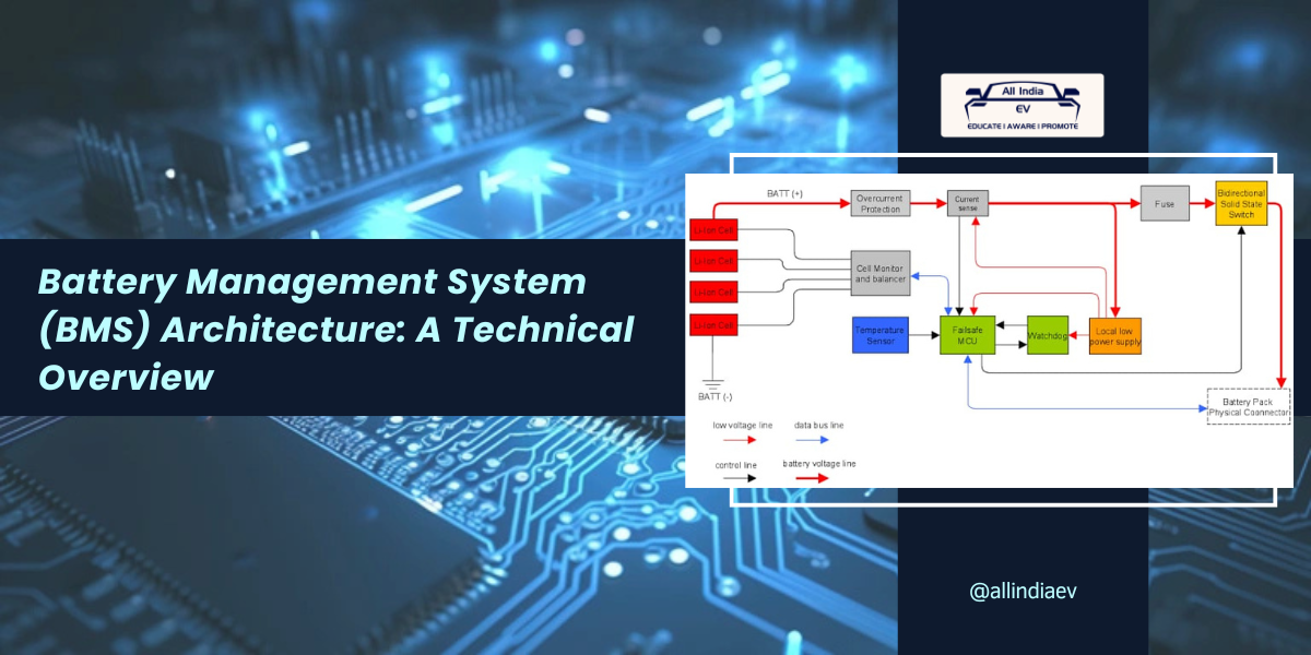
Battery Management System (BMS) Architecture: A Technical Overview
In modern electric vehicles (EVs), the Battery Management System (BMS) is a critical component that ensures the safety, reliability, and performance of the battery pack. The BMS monitors and controls the state of the battery to prevent issues such as overcharging, over-discharging, and overheating. Based on the provided block diagram, we will walk through the essential components and functions of a typical BMS architecture used in EVs, referencing each major block from the image.
Key Components of the BMS Architecture
🔹 Li-ion Cells (Battery Cells): The foundation of the system consists of lithium-ion cells that form the battery pack. These cells are arranged in series or parallel configurations depending on the desired voltage and capacity. In this diagram, several cells are connected to the BMS circuitry, with a focus on maintaining a balance across individual cells to ensure uniform performance and prolong battery life.
🔹 Overcurrent Protection: Overcurrent protection is crucial in preventing damage to the battery pack. This block monitors the current drawn from the battery and ensures that it stays within safe limits. In the event of an excessive current, this circuit will disconnect the battery to prevent potential hazards such as thermal runaway or cell damage.
🔹 Current Sense: The current sense block is used to measure the current flowing into and out of the battery. Accurate current sensing is critical for determining the state of charge (SoC) and for estimating the battery’s overall health and capacity. This data feeds into the Failsafe MCU to ensure that the system operates within safe boundaries.
🔹 Cell Monitor and Balancer: The cell monitor and balancer is responsible for monitoring the voltage levels of individual cells within the battery pack. Lithium-ion cells can degrade at different rates, leading to imbalanced voltages across the pack. This block ensures that each cell is properly balanced to prevent overcharging or undercharging, which could degrade battery performance or cause safety issues.
The cell balancing process is vital to extend the life of the battery pack and maintain optimal performance. Active or passive balancing techniques can be employed here, depending on the complexity of the system.
🔹 Temperature Sensor: Temperature monitoring is critical for the safe operation of a battery pack. The temperature sensor monitors the thermal state of the battery cells. If any cell or region of the battery becomes too hot, the Failsafe MCU can take corrective action, such as reducing power output or shutting down the battery to prevent thermal damage.
More EV News

🔹 Failsafe MCU (Microcontroller Unit): At the heart of the BMS is the Failsafe MCU, which processes data from the current sensors, voltage monitors, and temperature sensors. It executes control algorithms to manage the battery’s charge and discharge processes. In the event of an abnormal condition (e.g., overvoltage, undervoltage, or high temperature), the MCU can trigger protective mechanisms such as shutting down the battery or limiting current flow.
The MCU also communicates with the Watchdog and other BMS subsystems, ensuring that the system is operating under safe and controlled conditions.
🔹 Watchdog: The Watchdog ensures that the BMS functions correctly by continuously monitoring the system for faults or irregular behavior. If the MCU or any other component fails to respond as expected, the Watchdog can initiate a reset or other corrective actions to bring the system back to a safe operational state.
🔹 Local Low Power Supply: The Local Low Power Supply ensures that the BMS has a reliable source of power even when the main battery pack is not actively delivering power. This is important for functions like monitoring the battery during idle periods and ensuring the system is ready to react to faults at all times.
🔹 Fuse: The fuse serves as a primary safety device that protects the system from excessive currents or short circuits. If the system detects a fault condition or a dangerously high current, the fuse will blow, disconnecting the battery from the rest of the system to prevent further damage or hazards.
🔹 Bidirectional Solid-State Switch: The bidirectional solid-state switch is a key component in controlling the flow of current between the battery pack and the external load (e.g., the EV’s powertrain). It allows for the smooth switching between charging and discharging modes and can quickly disconnect the battery in the event of a fault. Solid-state switches offer advantages over mechanical relays in terms of speed, reliability, and durability.
🔹 Battery Pack Physical Connector: This is the interface through which the battery pack connects to the vehicle’s powertrain or charging infrastructure. It serves as the main conduit for electrical energy flow into and out of the battery pack. The data bus line connecting the physical connector to the rest of the system ensures that data such as current flow, charge state, and temperature can be monitored and controlled by the MCU in real time.
Flow of Operations in the Battery Management System
The flow of operations in the Battery Management System is a carefully orchestrated process designed to ensure the safety and efficiency of the battery pack while providing the vehicle with reliable power. Here’s how the various components interact in real time:
1️⃣ Startup and Initialization: When the battery pack is activated (e.g., when the vehicle is started), the Failsafe MCU initializes all components, including the temperature sensors, current sensors, and cell monitors. The system performs self-checks via the Watchdog to ensure that the sensors and other components are functioning correctly.
2️⃣ Real-Time Monitoring: During operation, the BMS continuously monitors the voltage levels of individual battery cells via the cell monitor and balancer. This data is transmitted to the Failsafe MCU, which analyzes the cell voltages to ensure that they remain within safe operating limits.Simultaneously, the temperature sensor monitors the thermal state of the battery pack. If a cell exceeds the temperature threshold, the MCU can reduce power output or shut down the battery to prevent thermal runaway.
The current sense block measures the current flowing into and out of the battery. This data is critical for tracking the state of charge (SoC) and state of health (SoH) of the battery, helping the MCU manage charging and discharging processes efficiently.
3️⃣ Cell Balancing: If any cells are detected to be out of balance (i.e., their voltage levels differ significantly), the cell monitor and balancer adjusts the charge distribution to bring the cells into alignment. Balancing can be either passive (dissipating excess energy as heat) or active (redistributing energy between cells). This ensures that the entire battery pack operates uniformly and efficiently.
4️⃣ Fault Detection and Protection: Throughout the operation, the Failsafe MCU continuously monitors the battery for potential faults. If the current sense detects an overcurrent condition or if a temperature sensor registers excessive heat, the MCU triggers protective measures such as disconnecting the battery via the bidirectional solid-state switch.
If the fault persists, the fuse serves as a final protective measure, permanently disconnecting the battery to avoid catastrophic failure.
5️⃣ Watchdog and Fault Recovery: The Watchdog monitors the system’s operation and ensures that the MCU and other subsystems respond correctly to commands and changes in the battery state. If the Failsafe MCU fails to respond within a predefined time window or encounters a fault, the Watchdog resets the MCU or triggers a system-wide safety protocol.
6️⃣ Shutdown: When the vehicle is turned off, the BMS performs a controlled shutdown. The Local Low Power Supply remains active to ensure that critical monitoring functions continue even when the battery is idle. This is important for preventing issues such as self-discharge or thermal buildup during long periods of inactivity.
Moving forward…
The Battery Management System (BMS) is a crucial component in ensuring the safe and efficient operation of lithium-ion battery packs in electric vehicles. The architecture, as depicted in the diagram, illustrates a comprehensive approach to monitoring and controlling the battery system, incorporating overcurrent protection, cell balancing, temperature sensing, and failsafe mechanisms.
The Flow of Operations ensures that the system works harmoniously to protect the battery pack and optimize performance, from startup to shutdown. By managing the battery’s health and performance in real time, the BMS contributes to the reliability, longevity, and efficiency of electric vehicles, ensuring safe and effective power delivery under various operational conditions. As EV technology advances, the role of the BMS in maintaining battery health and extending the operational life of battery packs will only become more important, securing a future of sustainable and reliable energy for electric transportation.


good