EV Engineering

Battery Management System (BMS) Architecture: A Technical Overview
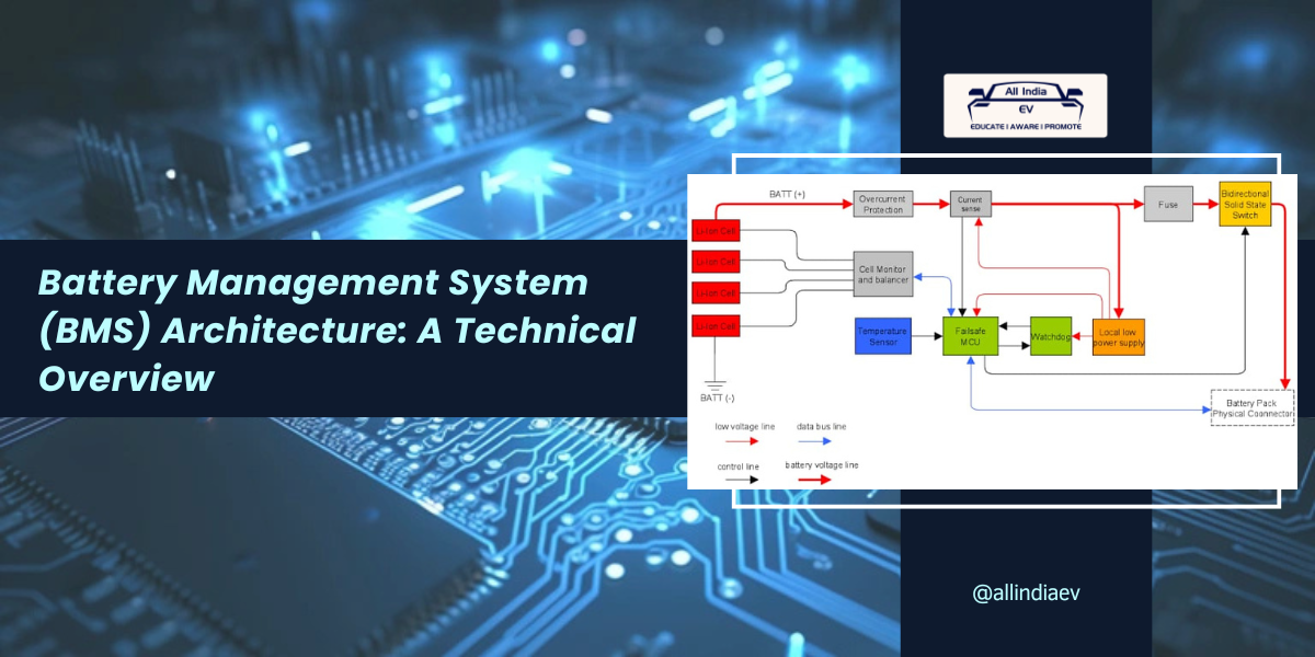
Battery Management System (BMS) Architecture: A Technical Overview In modern electric vehicles (EVs), the Battery…
LG Chem’s Innovation Could Revolutionize Battery Safety
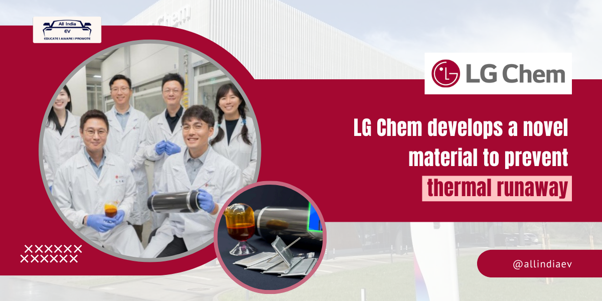
LG Chem's Innovation Could Revolutionize Battery Safety LG Chem, a global leader in advanced materials,…
EV Skateboard Explain: Types, Features and Manufactures
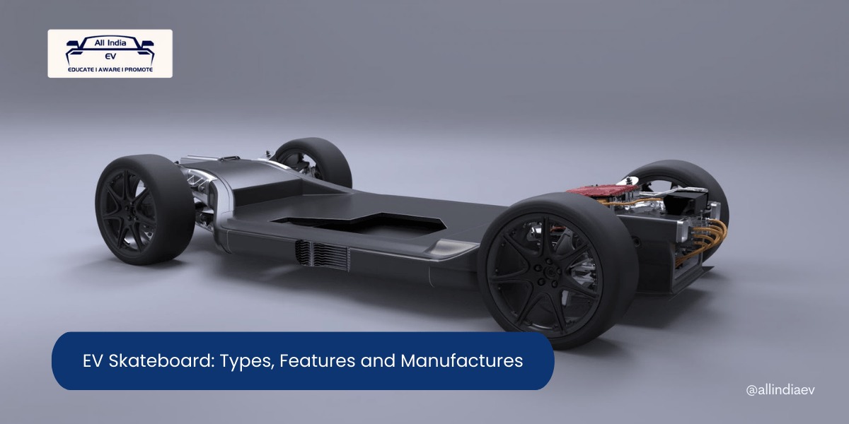
EV Skateboard Explain: Types, Features and Manufactures Electric vehicles (EV) are shaking up the automotive…
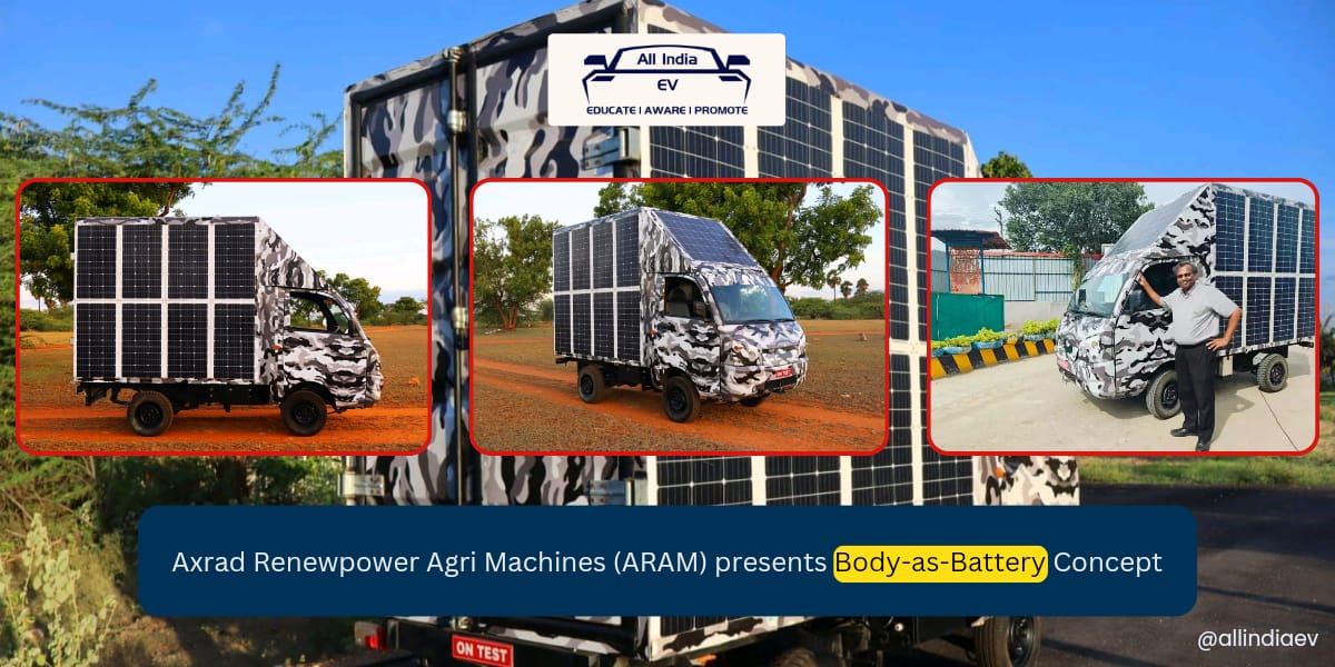
From BaaS to BaaB: A Paradigm Shift in EV Ownership
From BaaS to BaaB: A Paradigm Shift in EV Ownership Axrad Renewpower Agri Machines (ARAM),…
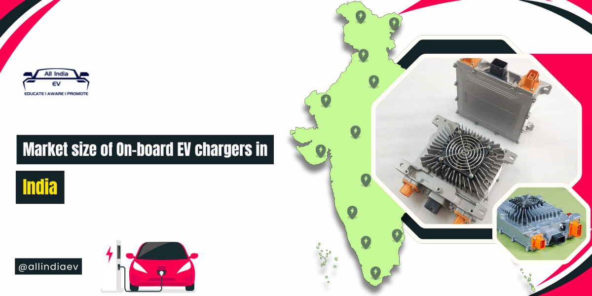
How an On-board Charger Powers Your Electric Vehicle
How an On-board Charger Powers Your Electric Vehicle The charger has a direct impact on…
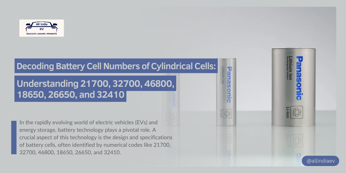
Decoding Battery Cell Numbers of Cylindrical Cells
Decoding Battery Cell Numbers of Cylindrical Cells: Understanding 21700, 32700, 46800, 18650, 26650, and 32410…
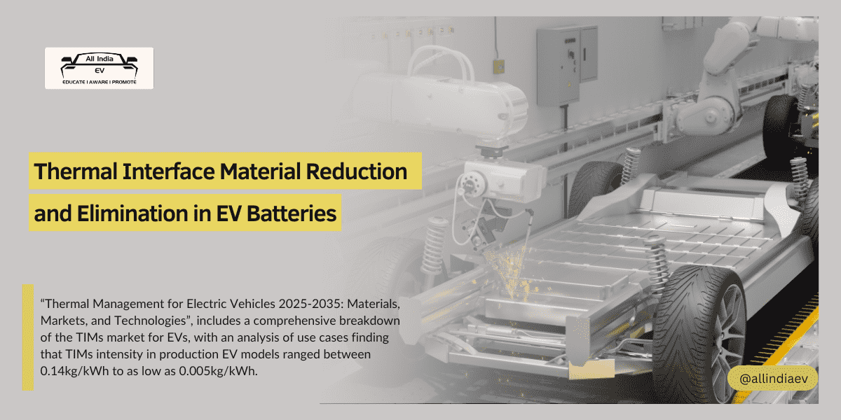
Thermal Efficiency Boost: Eliminating TIMs in EV Batteries
Thermal Efficiency Boost: Eliminating TIMs in EV Batteries In the development of electric vehicles, manufacturers…
Part 4: Experimental results
Part 4: Experimental results In lengthy and high-precision magnetic field measurement experiments, the inherent fluctuations…

Part 3: Experimental verification, Experimental setup
Part 3: Experimental verification, Experimental setup Cracks (or cuts, scratches) In the manufacturing process of…
Part 2: Flawless cells, Internal short circuit
Part 2: Flawless cells, Internal short circuit Flawless cells First, we conducted calculations for the…